+359 2974 39 76
hic@hic.bg

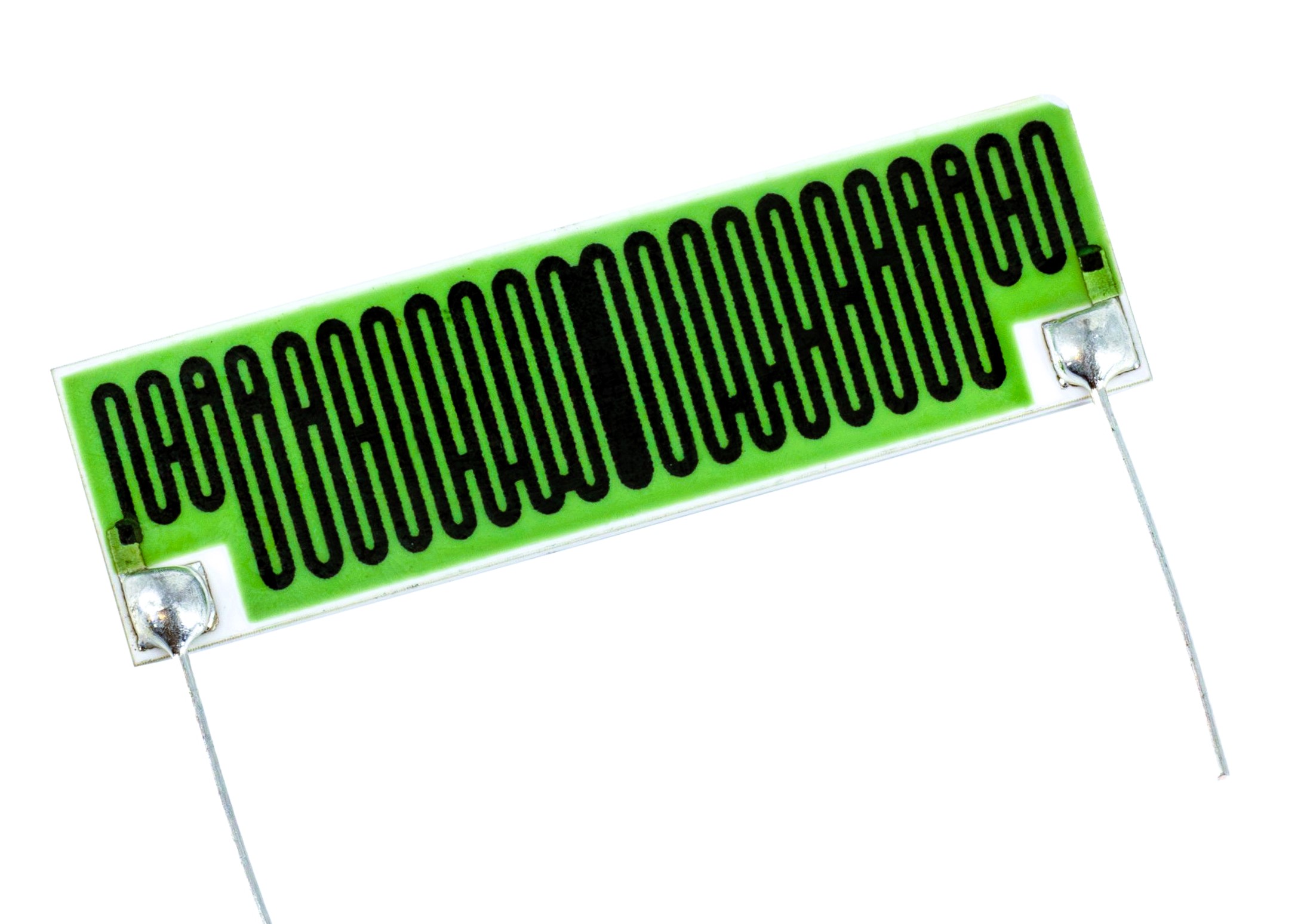
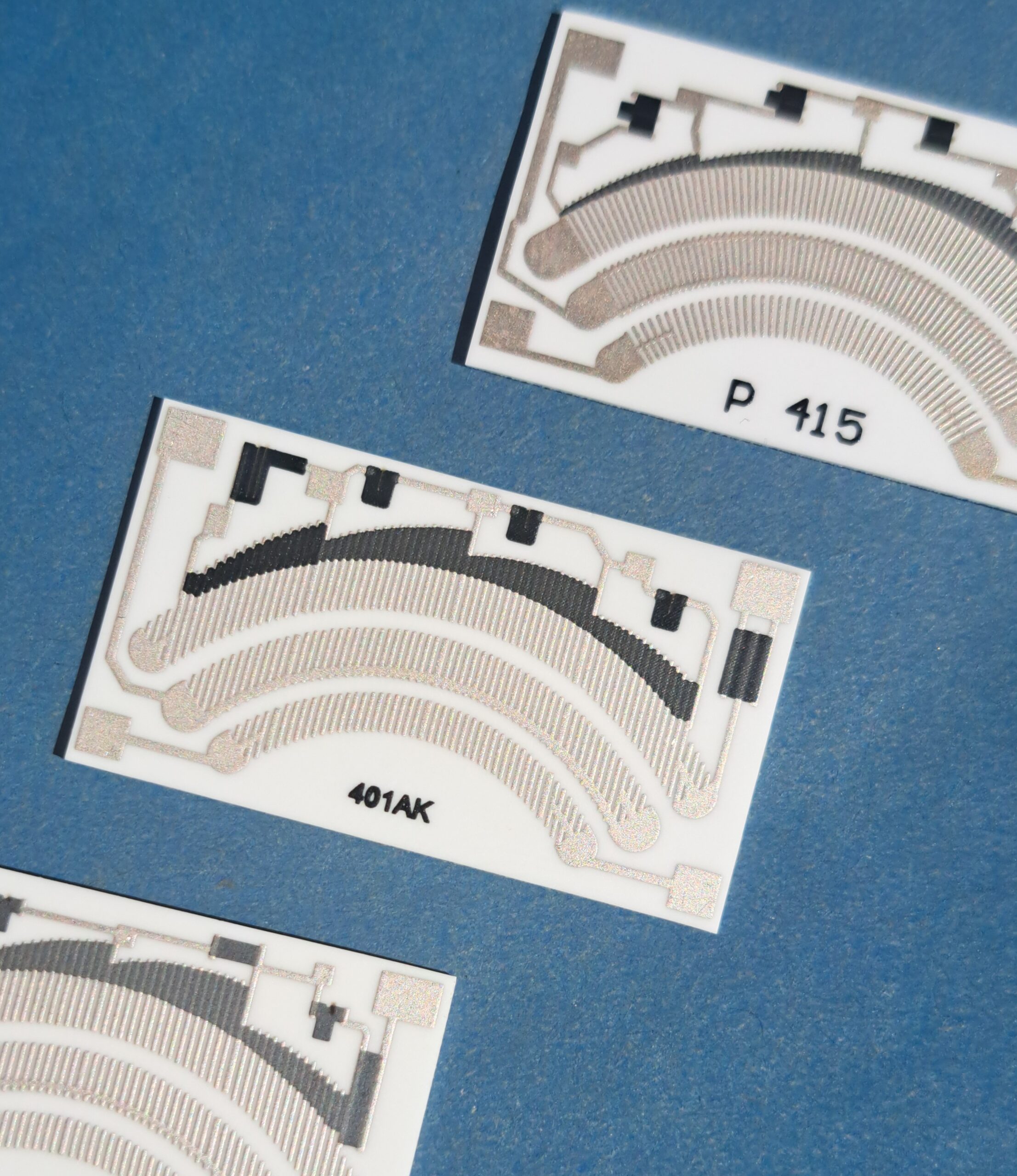
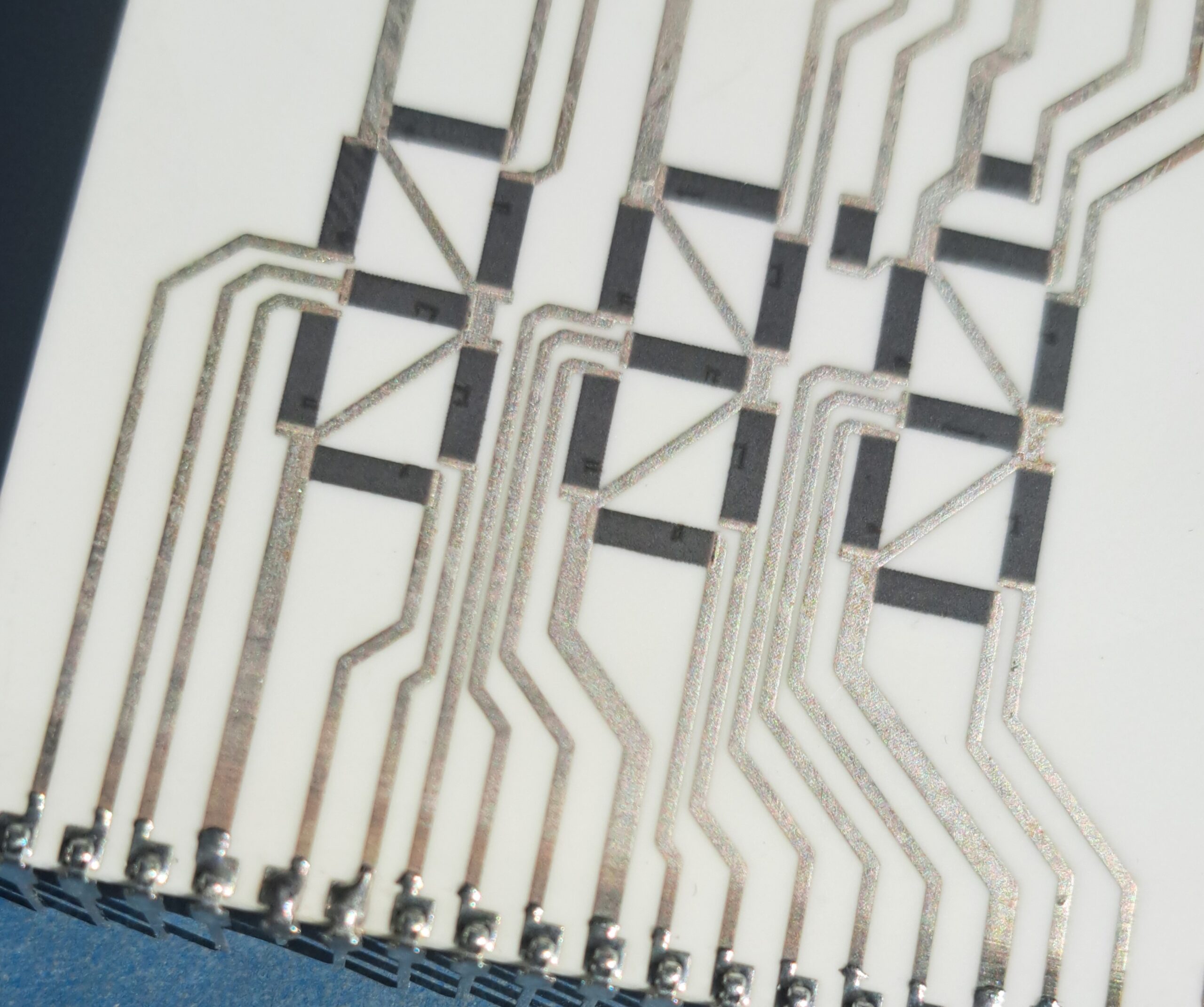
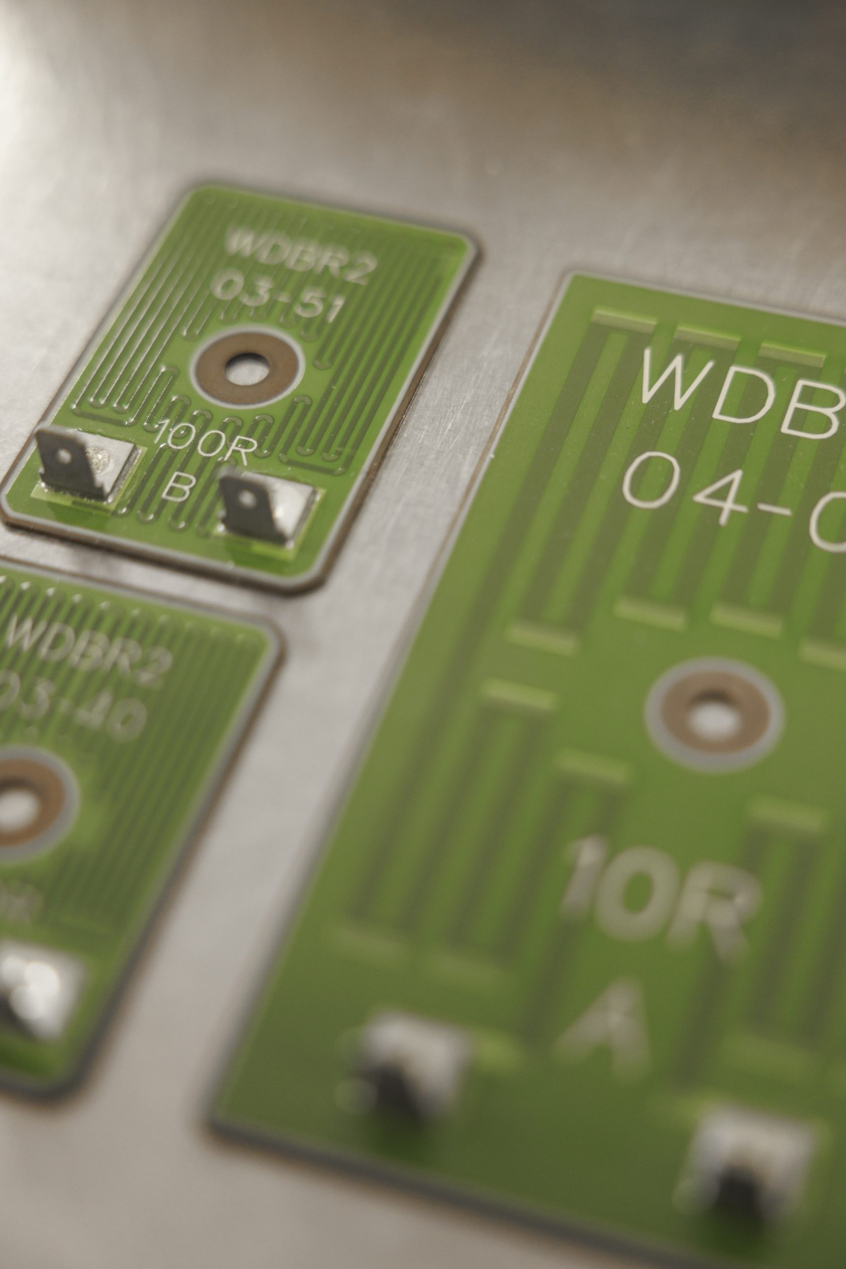
Thick-Film Resistor Networks

Resistance Range of the Integrated Resistors:
0.1Ω - 99MΩ
Resistance Tolerance and Ratio Between Resistors:
0.1Ω - 1Ω ±5%
1Ω - 10Ω ±1%
10Ω - 100kΩ ±0.5%
100kΩ - 10MΩ ±1%
10MΩ - 99MΩ ±5%
Temperature Coefficient of Resistance (TCR):
minimum ±50ppm/° C;
Maximum Power Dissipation:
2W/cm2;
Stability of Integrated Resistors at 70°C and Rated Load:
1000h ±0.1%;
Reliability:
10

Standard Configurations

Type A
Single-terminal resistors with a single-row lead arrangement (SIL) at 2.54 mm pitch, epoxy protective coating, marked common terminal
Type B
Resistors with separate leads, single-row lead arrangement (SIL) at 2.54 mm pitch, epoxy protective coating
Type D
Resistors with separate leads, double-row lead arrangement (DIL) at 2.54 mm pitch, protective polymer coating

Designation

a b ccc d
General Form of the Designation
a
Type
b
Number of Resistors
c
Resistance Value (3-Digit Code)
d
Tolerance ( D - 0.5%; F - 1%; G - 2%;J - 5%; K - 10%; M - 20%)
For example: A 9 103 J – 9 resistors, 10 kΩ, 5% tolerance, SIL external lead arrangement, marked common terminal

High-Voltage Resistors

Single Resistors, Voltage Dividers, Custom Configurations
Maximum Operating Voltage: 25 kV
Hybrid Integrated Circuits JSC
© 1996 – 2026 | HIC JSC.
Design & Development Avinir Web
envelopephonemap-marker linkedin facebook pinterest youtube rss twitter instagram facebook-blank rss-blank linkedin-blank pinterest youtube twitter instagram